Welcome
To
Robotics World

Wednesday, 30 November 2016

Build a Simple Walking Robot Leg


Build a Simple Walking Robot Leg
Here is probably the simplest robot leg that allows forward and backward and up and down movement. It only requires a toy geared motor and some other miscellaneous stuff  to build. I didn't have to buy anything to build this project.
The problem with leg movement is that as the leg moves forward or backward it also needs to go up to prevent dragging it's foot on the floor. The wheel has all the correct motions built in and it is just a matter of attaching the leg to the wheel in such a way as to take advantage of that range of motion (using crank/slider mechanism).


The build log is just a generalized discussion of photos of my build as everyone's use of materials would probably be very different.

Future modifications: 
1. I plan to add a knee joint to the leg that will lift the foreleg or bottom of the leg up as the thigh moves forward or back thereby making it easier to step over obstacles..

2. It would be really cool to add a solenoid to lower and raise the pivot point of the leg. This would reduce and enlarge the leg stride on the fly making a way to increase and decrease the efficiency of the robot leg while it is moving.

3. It would also be interesting to put 6 of these legs together and see how a robot can move without using computer control to coordinate the legs movements.

4. Put a shoe on the leg - noticed it is slipping a bit on the carpet.Step 1: Mount motor on tether
Mount motor on tether
The motorized wheel comes from a toy construction truck. I mounted the motor on an acrylic ruler by drilling two holes through the ruler and into the motor gear box. Be careful that you do not drill into the gears. Then use self tapping or wood screws to attach the ruler, which serves as the tether, to the gear box. Note I hotglued and zip tied the motor wires to the gear box so that they don't get pulled out.

After that I drilled and bolted a spacer which is the plastic box (gotten from half of a power supply box) to the bottom of the ruler or tether.

Onto the spacer I bolted another short piece of acrylic ruler which will serve as the mount for the leg pivot point.

Tuesday, 29 November 2016

How to make a two-legged walker

How to make a two-legged walker with few degrees of freedom.”

One thing I’ve always been fascinated by is making walking biped robots with limited degrees of freedom (DOF).  Each degree of freedom requires a servo, and servos strong enough for a biped walker tend to be expensive.  In addition, more servos means more weight, and more weight requires stronger servos; this explains why any good humanoid robot (with 16 DOF or more) is likely to cost $1000 or more.  For people new to the hobby, this is likely to be too big an investment to make right away.  It’s so much better to start smaller, and work out all the command & control issues while feeding one’s growing addiction with a lower-cost robot.
This leads to the natural question: how many servos do you really need to make a walking biped?  In this blog post, I’ll attempt to answer that question with a quick survey of low-DOF biped robots.

One Servo

With a single servo, you basically can’t make anything better than a wind-up robot toy.  These essentially have overlapping feet, accomplish via long prongs that stick out from the toe and heel of each foot, towards the other foot.  As a result, the robot’s center of gravity is always over the support polygon (the area on the floor enclosed by the supporting foot), and it can easily stand on one foot or walk without falling over, using only a single motor to cycle both feet.  But overlapping feet is cheating, in my book, and even with that cheat, such a robot can’t turn; it can only walk forward and backward.  ‘Nuff said.

Two Servos

You might expect that two servos isn’t enough for a true biped either.  But you’d be wrong.  In 1998, hobby roboticist David Buckley developed a two-servo robot called BigFoot.  Bigfoot uses one servo to drive the feet alternately back and forth, using parallel linkages to keep the feet parallel with the floor.  Then it uses a second servo, with another linkage to each foot, to tilt both feet side to side.  This allows the robot to shift its weight from one foot to the other — a task made easier by purposely designing the robot to be tall, with a high center of gravity (COG), so that a smaller tilt angle results in a big horizontal shift.  The robot can walk stably, and turn by skidding its feet.  This ingenious design has since been commercialized as the Parallax Toddler.  David has since made other variations of this design, such as Bambino.

Three Servos

Three-servo bipeds are pretty rare.  One example is “Dead Duck Walking” by Frits Lyneborg.  This uses one servo to tilt both feet sideways, one to twist them in and out, and a third to shift a weight (the batteries) side to side to aid with balance.
Though I haven’t seen it done yet, another idea for a 3-servo biped would involve 1-DOF legs that can step forward or backward, plus a counterbalance servo to shift the COG over the supporting foot.  For 1-DOF legs, see this 2008 paper by Liang, Ceccarelli, & Takeda. Or, consider using something like a Klann linkage.  In either of these cases, you have the problem that the lower leg does not maintain a constant angle with respect to the ground, so you can’t just bolt on a foot; you’d need to add some sort of parallel linkage to the leg to keep the foot level.  But it just might work.

Four Servos

David Buckley, the mechanical wizard behind BigFoot, has written a wonderful treatise on minimalist biped walkers.  In it, he describes the “Aesir” series of 4-servo bipeds, developed in 2002.  The first was Loki, which uses a servo at each hip to yaw the leg around the vertical axis; and another in each ankle to tilt (roll) the foot sideways.  Using the ankle servos, Loki can shift its weight onto one foot, then use both hip pivots to move the other foot forward or backward to take a step.  Thanks to the hip pivots, it’s also able to turn without skidding.
The Loki design has since been copied widely.  Most famous is the LynxMotion Brat Jr., which many people have built in various forms (including my own 4S-1).  The Hovis Lite kit includes plans for a Loki-style biped, and similar beasts have been built using Bioloid parts.  Thingiverse even has a couple of printable part kits for Loki derivatives, including a cute one called “Arduped.”
David went on to make another robot called Frea, with a different servo arrangement: the hip servos swing the legs out sideways, and the ankle servos yaw around the vertical axis.  With this arrangement, Frea is able to stand up from any starting position.  However, to make it work, David had to use overlapping feet — which is still cheating in my book, but an impressive robot nonetheless.  (See also Thor, which uses essentially the same design, but has a cool reverse-knee mech look.)
Are there other arrangements of four servos that can walk well?  One can easily imagine use parallel-linkage legs, like in BigFoot, but with an independent servo moving each leg forward and back.  This, combined with the ankle tilt servos, would enable walking similar to BigFoot’s, but more versatile.  (Now that I think of it, I’ve pretty much described TecFoot minus the fifth servo — see below.)  However, it’s still not as versatile as the Loki design, since it can’t pivot its feet to turn.  If you have any other ideas (or references) for 4-servo walkers, please post ’em in the comments below.

Five Servos

Despite the risk of sounding like a David Buckley cheerleader, I have to turn to him yet again for a good example of a 5-servo walker.  This is TecFoot, a tall walker that uses two servos per leg, to independently tilt at the ankle, and swing forward/back; plus one more servo which splays the feet inward or outward together.  That’s accomplished by mounting each leg on a hinge, and using a servo in the center of the body to move these hinges in or out at the hip.
As with all of David’s designs, this is a very clever and efficient use of servos, based upon the recognition that you don’t much care about the orientation of the foot that’s in the air; only the supporting foot matters.  (And when standing on both feet, there’s not much point in pivoting them at all.)

Six Servos

By this point, we’re stretching the definition of “minimal” quite a bit.  Making a biped with 3 DOF per leg is fairly easy, and is exemplified by the LynxMotion BRAT.  This design uses hip servos to swing the leg back and forth; knee servos to bend like knees do; and ankle servos to tilt the feet sideways.  So, using the ankle servos, the robot can shift its weight onto one foot, then use the hip and knee to take a nice big step with the other one.
Because this design lacks any rotation about the vertical axis, it has to turn by shuffling, much like the 2-servo BigFoot.  There are undoubtedly many other 6-servo configurations that would also work.  Considering just the rotation axis, there are 3^3 = 27 different arrangements of the servos for each leg — and that’s not including details of the placement, nor variations that use linkages.  So, that might have to be a topic for another post.
What do you think?  Have I misse

Monday, 28 November 2016

How I built a neural network controlled self-driving (RC) car!

Recently, I have been refreshing my knowledge of Machine Learning by taking Andrew Ng's excellent Stanford Machine Learning course online. The lecture module on Neural Networks ends with an intriging motivating video of the ALVINN autonomous car driving itself along normal roads at CMU in the mid 90s.
I was inspired by this video to see what I could build myself over the course of a weekend. From a previous project I already had a cheap radio controlled car which I set about trying to control.
 

The ALVINN system captures video frames every couple of seconds and passes them to a (series of) neural networks which have been trained by watching a human drive in similar environments. The trained neural network can then be passed live video frames and will predict how to steer to stay on the road ahead! I figured I'd do the same with my scaled down version. I needed a system which could operate in two modes:
  • Record — The system captures video frames and the control input from a human driver (me!) and records them for later use to train the neural network.
  • Drive — Captures live video frames, passes them to a trained neural network which makes predictions about how to drive/steer which are sent to the car by radio control - hey presto, a self driving car!

Design

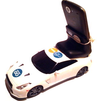
The system should be able to record video from the car, pass frames to a neural network and control the car's steering / motors. The "obvious" way to do this might be to mount an Android phone on the car, gathering video frames and making neural network predictions locally on the device, hacking the car to be controlled from the onboard phone using an Arduino based Android ADK board, with data recorded and transferred to a computer for training.
Unfortunately, ADK boards require enough juice to keep the phone powered over USB and the weight of additional batteries would make this cheap and cheerful car struggle. Instead, I opted for a design which barely modified any of the components involved:

Anatomy of a self-driving RC car

Driver app running on Mac OS X
The system consists of:
  • Android phone — mounted on the car, captures video frames of the road ahead using its built-in camera at ~15 fps. An app running on the phone connects to a server running on a laptop computer via wifi and streams 176x144 grayscale video frames across the connection.
  • Computer — runs a little Java app called "Driver" which acts as both a TCP server, receiving streamed image frames from the phone and a user interface allowing a human driver to control the car with the cursor keys or mouse. In record mode, the video frames are saved to disk, labelled with the current control input coming from the human driver. The neural network is trained using these labelled frames in a separate environment on the computer. Trained parameters are saved out to files which are in turn read by the Driver app... which in auto mode can feed incoming video frames directly to the neural network and steer according to its predictions, by sending instructions over a serial interface connected to an...
  • Arduino Uno — connected to the computer via USB and hacked to connect to and simulate keypresses on the car's radio controller PCB (as described below).

The Neural Network

As on the ML course, the Neural Network is trained using an octave program, and I didn't stray too far from the set up used there. The diagram below shows the architecture of the network I used. Here we have 25345 units in the input layer - 25344 units which are fed the brightness value of an individual pixel in the 176 x 144 video frame (176x144 was the lowest resolution the camera on my phone supported in preview mode) and a bias unit. I chose to use 64 non-bias units in my hidden layer - this choice is fairly arbitrary, but I found that my initial choice of 256 took a pretty long time to train, and 8 units were not expressive enough to drive the car successfully. Crucially, there are four units in the output layer - one corresponding to each of the instructions we can send the car - go forwards, backwards, left or right.


Here comes the magic - the network is trained using backpropagation which produces weights corresponding to the contribution each input layer unit makes to the activation of each of the hidden layer units, and the contribution each hidden layer unit makes to the activation of each of the output layer units. There's no explicit image processing going on here - the network literally figures out what kind of patterns in the input video frames are useful in making decisions about how to drive the car, based on minimizing the numerical error between the current prediction and all of the recorded examples. The little frame at the bottom of the diagram below is a visualization of the weights assigned to each of the pixels in the input layer as they contribute to just one of the hidden layer units - you may be able to see here that this unit corresponds to some kind of edge detection in the middle distance broadly sweeping to the left or right.
To make predictions in auto mode, I also implemented the same network topology in Java (making use of the Apache Commons Math Library for linear algebra). NeuralNetwork.java contains the interesting code and is a generic neural net implementation you could use for any three layer network (and also contains code for parsing a RealMatrix from an octave .dat file). To test the correctness of this implementation, NeuralNetworkTest.java checks that the predictions from this code are virtually identical to those made with the same input data and network parameters under the octave implementation. The Driver app uses this Java implementation, set up with network parameters loaded from files written by the octave script at the end of the training process.

Radio Control with Arduino

For a previous project, I had controlled this car with a PS/2 mouse connected to an Arduino UNO. This time, I extended that design so that commands sent over the USB / Serial interface could be sent to the car via its original controller.

Choice of car

I bought the cheapest RC car I could find - this one if you want to get the same - it cost about £10. Pretty much any cheap car will do, as long as the controller is a push button on/off type rather than a continuous control. The hack is pretty simple - modify the radio control unit (car stays unmodified) so that instead of a human pressing the buttons, the arduino board will press them for us based on the value received over the serial port.

Figure out how the RC controller works

Take the RC controller apart and figure out how it works. Expensive radio controlled cars have servo motors for steering and variable speed control on their main motor, but a cheap car like this just has on/off switches for each of forward / backward / left and right. You can follow the tracks from each side of each switch to the nearest solder joint on the original board. Find the pads for each switch and confirm with a multimeter that the solder joints are the correct ones - when the switch is pressed, the resistance between the two relevant joints will be zero. Once you've identified the joints that matter, attach patch wires to each point with a soldering iron. The controller I used had a common ground (blue wire in the photo below) which the pads for up/down left/right were being connected to when the relevant switch was pressed. In the photo, you can see that I have traced these connections back to the point where solder joints already existed and attached wires (orange, yellow, white, red). It is a good idea to use different coloured wire for each of the directions so you can keep track of which one is which when working on a breadboard.

Once I got it working, I chose to remove the PCB from the original controller housing altogether and instead of powering it with 2 x AA batteries, I fed it 3.3V from the Arduino board (so all power for this unit comes over USB from the computer). To switch the connections from software running on the Arduino board, we need to build a simple circuit on a breadboard to allow an Arduino pin to drive each 'button' without being physically connected in a circuit [1] - we can use optical isolators for this - the opto-isolator part I used was a 4N35. You need to build the below circuit four times (once for each direction). The common ground from the RC controller will be connected to pin 4 of the 4N35 and the direction switch lead you soldered on will be connected to pin 5. The Arduino pin for turning on the controller switch for the given direction will be connected to pin 1 on the 4N35.

Fully built out on a breadboard it will look like this:

Arduino sketch

Finally, we need a firmware sketch to run on the Arduino board. You can see the full source for this on github, but the key part is this little section in loop() :
 if (Serial.available() > 0) {
    incomingByte = Serial.read();

    left = right = forward = back = LOW;
    if (incomingByte & 0x01) {
      left = HIGH;
    }
    if (incomingByte & 0x02) {
      right = HIGH;
    }
    if (incomingByte & 0x04) {
      forward = HIGH;
    }
    if (incomingByte & 0x08) {
      back = HIGH;
    }
    ...
    digitalWrite(leftPin, left);
    digitalWrite(rightPin, right);
    ...
  }
Which reads a byte from the serial interface and decodes it to determine which buttons to push on the remote control which are written out as HIGH signals on the arduino output pins connected to the opt-isolators above. You may also notice in the source that I chose to pulse the forward direction for 250 ms followed by a 500 ms pause - this was done simply because the car I used was very fast and difficult to drive round a small circuit - you might like to experiment with different values or remove this altogether if you try with a slower car.
And, putting it all together, here's another video of the car in action:

Sunday, 27 November 2016

Neural Networks Beat Humans

Neural Networks Beat Humans
Another neural network breakthrough has been announced by Microsoft Research. Its neural network now outperforms humans on the 1000-class ImageNet dataset.

Neural networks have achieved amazing results in the past few years, but until now, when it comes to visual classification, humans were better. When set the task of classifying 100,000 test images humans achieve a 5.1% error rate. Now the latest neural network has achieved a 4.94% which is a significant improvement on the previous best GoogLeNet's 6.66%. 
Microsoft Research's Beijing team lead by  Jian Sun and Kaiming He are the same team that applied the vision resolution pyramid to speed up the calculation of deep convolutional networks. This time their improved result is based on what looks like a minor tweak. Many neural networks make use of rectifier neurons that don't output a signal until a threshold is reached. After the threshold the neuron simply reproduces the input i.e. it's linear. The new idea is add a parameter to that changes the behaviour so that the rectifier is "softer". Even in the cutoff portion its characteristic it still passes a reduced signal. This is called a Parametric Rectified Linear Unit (PReLU) and it seems to make the network better for very little extra computational cost - one parameter per neuron. 
The reason that the PReLU is expected to be better is that it avoids having to use zero gradients in the backpropagtion algorithm - something that is well known to slow down learn. Apart from the change in design nothing else has to change and the extra parameter can be added to the backpropagation's gradient descent. 
When they tried out the new architecture they found that there was a tendency for early layers to have larger values of a, which made the neurons more linear; and later stages to have smaller values of a, gradually becoming more non-linear. This can be interpreted as the model keeping more information in the early layers and making more classifications and distinctions in later layers. 
A second, and more technical, improvement is to the initialization of the weights. In most cases neural networks are initialized to a random state which in some cases can make training impossible because the learning gradients become very small. There are some schemes that assign "good" random starting weights but none that apply to rectified units. By an analysis of the PReLU neuron you can arrive at a recipe for a good random set of initial weights. 
In some experiments, it was observed the the new initialization allowed models that failed to converge with the original initialization methods not only to converge but also to show good results. 
Putting all of this together allows for deeper neural networks that are faster to train. It is worth adding that training takes 3 or 4 weeks using GPUs. 
Things the network got wrong

Neural networks are now better than humans at classifying images. However the nature of the advantage is interesting. Humans are good at general recognition - it's a dog or a cat are conclusions reached very quickly, but which breed of dog or cat may be be beyond the human's ability. The neural network, on the other hand, takes almost as much work in learning the coarse-grained differences as the fine distinctions.
To quote from the end of the paper:
While our algorithm produces a superior result on this particular dataset, this does not indicate that machine vision outperforms human vision on object recognition in general. On recognizing elementary object categories (i.e., common objects or concepts in daily lives) such as the Pascal VOC task [6], machines still have obvious errors in cases that are trivial for humans. Nevertheless, we believe that our results show the tremendous potential of machine algorithms to match human-level performance on visual recognition.
We still seem to be an age of development where almost alchemical tinkering provides worthwhile gains. We seem to have discovered that neural networks actually work but we still aren't sure exactly what works best. 
The network got this right - most humans just see a dog. 

Saturday, 26 November 2016

Robotic Arms & Grippers

Robotic Arms & Grippers

Lynxmotion AL5D Robotic Arm
OWI-535 Robotic Arm Edge

Items 1-24 of 50

GridList


Popularity


24
  1. 1
  2.  
  3. 2
  4.  
  5. 3
  6.  


  • Popular Posts